Network Routing - A Deep Dive
A Primer

Routing is one of the most critical concepts in networking, yet it is challenging to understand. In this post, I break down the concept of routing from the very basics to the most advanced routing tables that power the Internet. I also give an example of manipulating network routes to solve interesting problems.
If you enjoy network engineering, check out my premium courses. I discuss networking, backend engineering, databases, and operating systems in depth.
The Birth of Networking — Data Links
The initial requirement behind networking is for two directly connected machines to communicate with each other. To build that out, each machine was equipped with a unique identifier called the MAC address (Media Access Control), a 48-bit address assigned to the Network Interface Card (or NIC) to which either an Ethernet cable or a WIFI radio antenna is located. An example of a MAC Address E8:EB:11:0F:49:25
When machine A wants to send a message to machine B, it creates a frame and puts the destination MAC address, the source MAC address, the data, and some other information. Here is an example of an Ethernet frame.
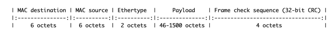
The WIFI frame 802.11 looks slightly different but still has the source and destination MAC, plus other fields. We can talk about that in another post.
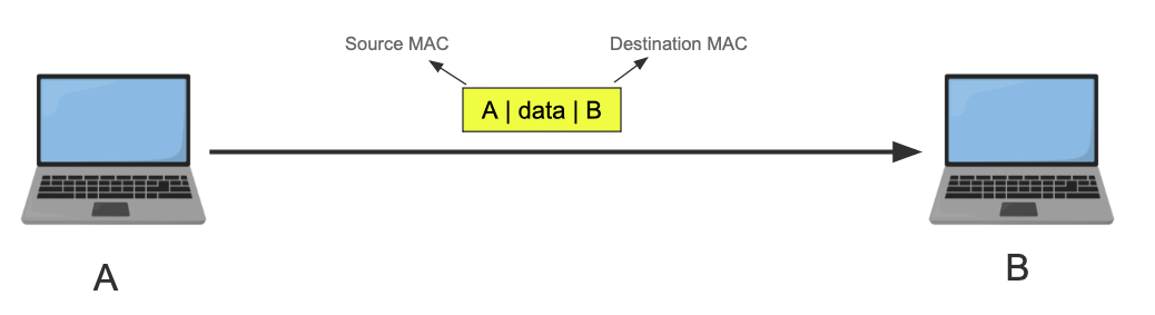
From now on, I’ll simplify the frame and only include the source MAC, the destination MAC, and the data. I’ll also use letters instead of 6 bytes for the MAC address. Source MAC is always on the left side, the Destination MAC is on the right, no matter the orientation.
Here is A sending B a message in a frame.
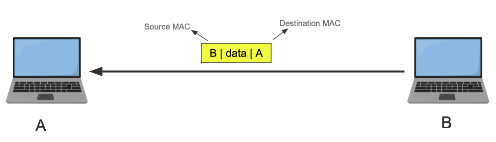
B can reply to A because it knows its address. It doesn’t have to, though.
The frames are sent as electrical pulses (in the case of Ethernet), radio waves (in the case of Wi-Fi), or light (in the case of fiber optics). Once received, the receiver machine’s NIC transforms the signal back to the binary frame format, and it checks if the destination MAC address matches its own NIC. If it does it passes it to the OS kernel, if not it drops the frame*.
You might say, “who does the checking and comparing of the MAC address?” and it is such a fantastic question. You see the NIC itself has onboard logic to do that. This check can also be skipped by putting the NIC in promiscuous mode, which means allow all frames in regardless and let the kernel do the filtering instead. Which is useful for virtual network interfaces where one physical NIC exists, but the machine has tons of VMs, containers etc each with different MAC Address.
This is the most basic level of communication known as Layer 2 or the data link layer, and is only possible because the two machines have a direct link. No guaranteed delivery, no retransmission, only some preemptive checksum.
Linking Multiple Machines
So how do we connect multiple machines? We can connect all the devices to a central device that has multiple ports and have that device forward the frames to the rest of the devices. Here are two devices that can do this.
Hub
A hub is a device that has multiple ports, we connect devices that want to communicate with each other to the hub. Here is a simple diagram where 4 devices, A, B, C, and D are connected to a hub.
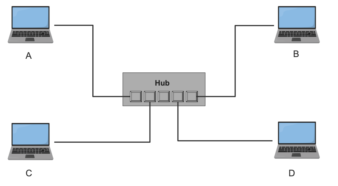
The hub repeats the frame it receives from one port to all other ports (except the one it got the frame from). All machines drop the frame except the one the frame is targeting.
This diagram illustrates sending a frame from A to B. The frame will arrive at the hub, and it will repeat the signal to all other ports. All machines receive the frame and drop it except B.
You can see the waste behind using a simple hub, which repeats the signal. We can introduce some intelligence into the device. Meet the switch.
Switch
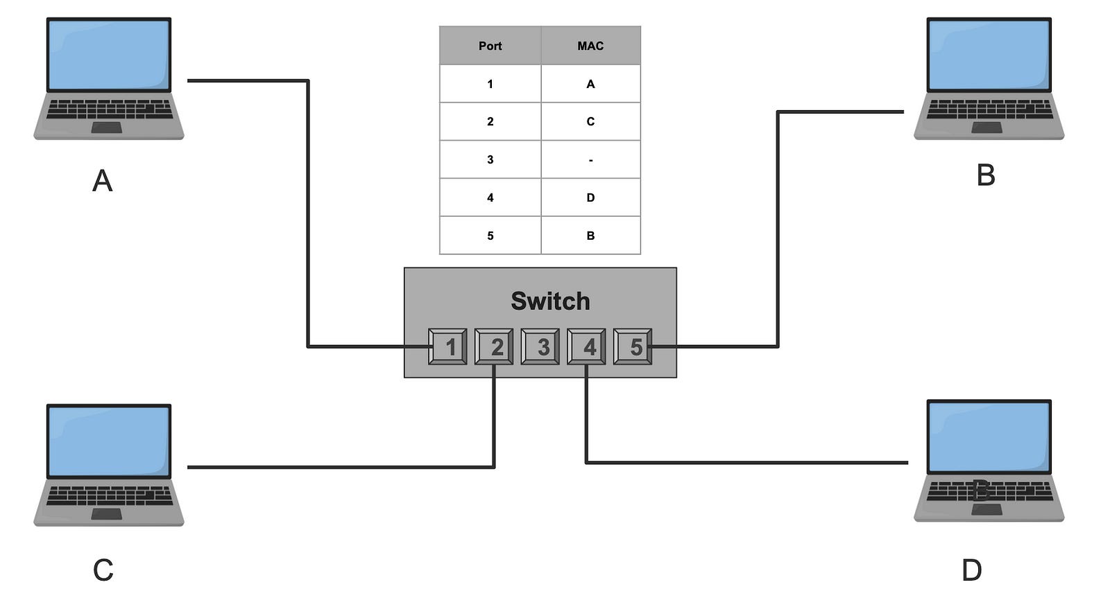
A switch acts similarly to the hub, but it has logic that enables other features. The switch remembers which MAC address is on what port by parsing the frame and storing a map between the MAC and the port it is connected to. The assumption here is that machines have already sent at least one frame to identify themselves. Here is an example of the same network with the switch.
Note: it is possible that a port can record multiple MAC addresses, think of a switch connected to another switch. It is a one to many relationship.
If A sends a frame to B, the switch receives the frame on port 1, looks up the destination MAC address in its mapping table to find the destination port, and forwards the frame to port 5, which leads to B. This reduces unnecessary traffic.
What if for some reason the switch doesn’t have the destination MAC address in its local mapping table? In that case, the switch acts like a hub and broadcasts the frame to all its parts except the input one.
The sky is the limit here. You can think of the rules to add here, prevent two machines from ever connecting, set bandwidth limit for certain machines, set permissions, security etc. this is what is referred to as virtual local area network or VLAN. Also just like any cache, that switch mapping table can get out of sync, needs to get updated and maintained, can get large which may require indexing. Sounds like a database problem. To learn more about the fundamentals of database engineering
https://databases.win
Why MAC Addresses don’t scale
Whatever we have so far is great for local area networking. However, with thousands of machines connected, even with switches, the connectivity grow so large. Eventually, each switch needs to know every other machine in the network to forward the frames correctly.

It is a classic database problem. In database engineering, we try to avoid large data by breaking it into smaller partitions. Networking is no different, we break large networks into smaller partitioned networks. These partitions are called subnets.
The problem is we have no way to partition using the existing addressing system with the MAC address, it is just a random 48-bit number. There is no way to group a collection of MAC addresses and place them into a “partition” without another data structure or table.
That is why we need a new addressing system. An address that when I look at it, I immediately know what partition, or what subnet it belongs to.
Meet the IP Address.
IP Addresses
To fix this, we introduced the Internet Protocol (IP), a brand new logical layer 3 on top of layer 2. Layer 3, or the Network layer, has a brand new addressing system known as the IP address. But what is special about this new address compared to the MAC address?
An IP address has two parts: the network and the host. This structure allows us to eliminate a whole group of networks and devices. Knowing the IP Address, I can know what network it belongs to and only send the message to the NIC that knows that network. Let us clarify this.
IP Networks
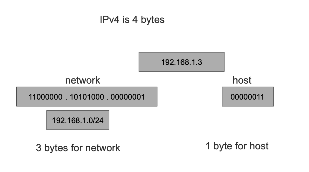
I’ll cover IPv4 in this post, which has 4 bytes (32 bits). We assign however many bits of the 32 bits for the network (N), and the remaining bits go to the host. We then pick a value for the network bits; the format of a network is a.b.c.d/N. The number of hosts is the remaining bits 32-N 2^(32-N). Every network has a mask that, when applied to an IP Address, we get its network. The network mask is where all the network bits are set to 1.
An example 192.168.1.0/24 defines a network that starts with IP 192.168.1.0 and ends in 192.168.1.255, note that the first and the last addresses are reserved and not used for actual hosts. 32–24 is 8, 2⁸ is 256 -2 results in 254 hosts. The network mask in this case is 255.255.255.0.
Given a network and an IP address, we can know if that IP belongs to that network. Let us see some examples.
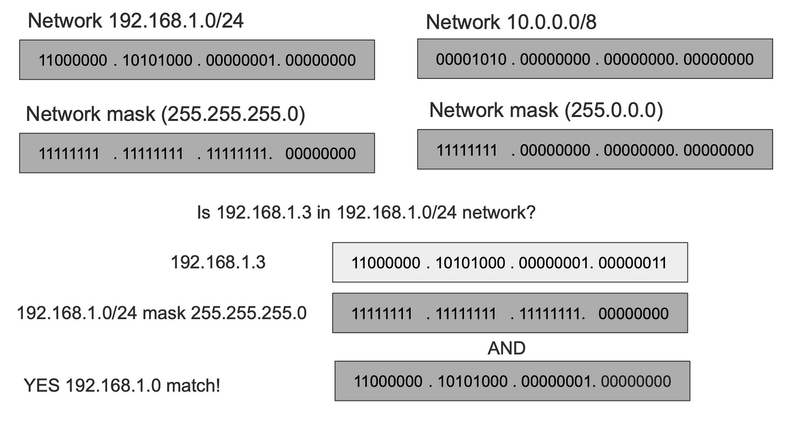
Take two networks 192.168.1.0/24 (mask 255.255.255.0) and 10.0.0.8 (mask 255.0.0.0), to know if an IP address is in 192.168.1.0/24 we apply its subnet mask with AND operator, and if the output matches the network, it means the IP is in the network. Let take an example is 192.168.1.3 is in the 192.168.1.0/24
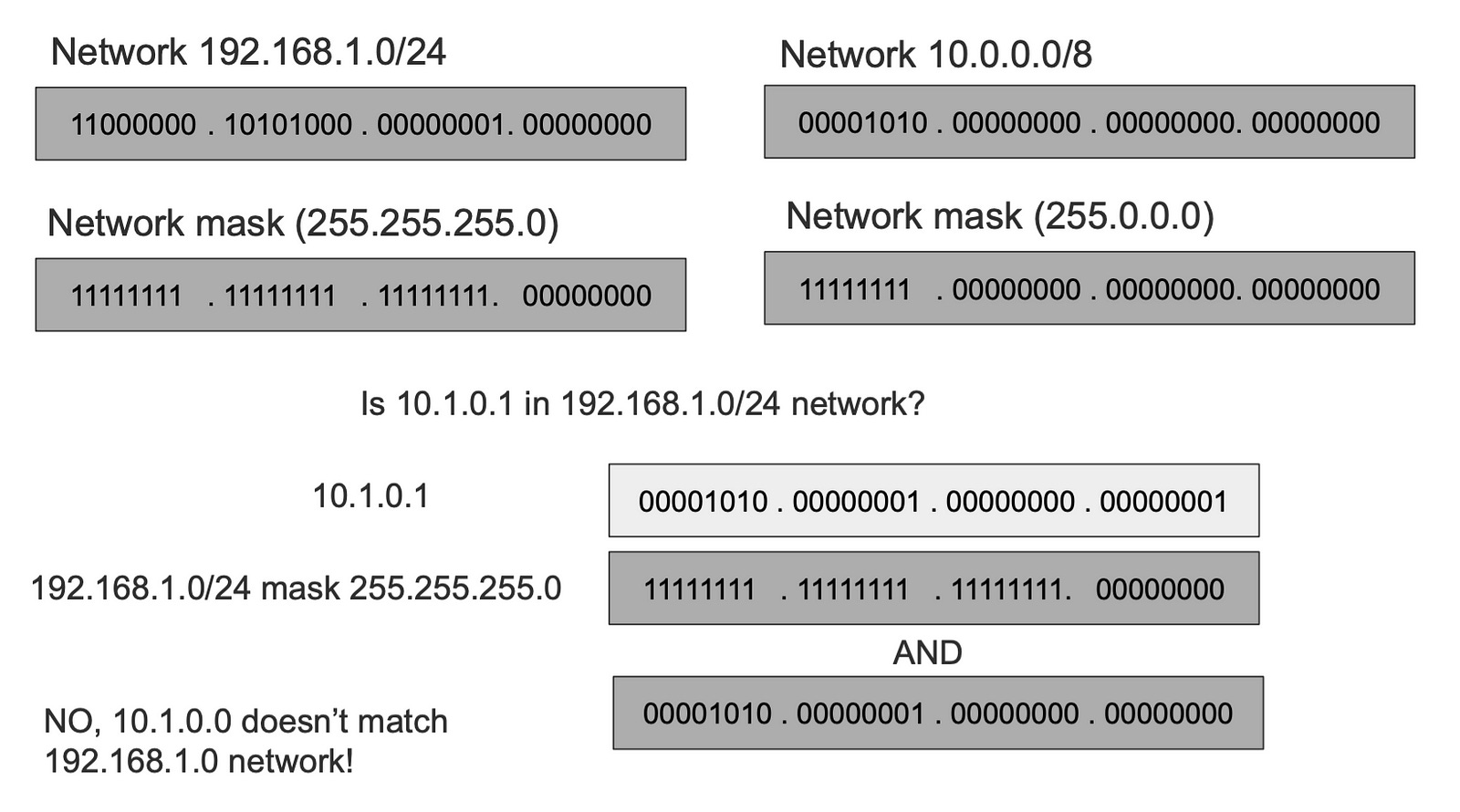
To check if the IP address 10.1.0.1 is in 192.168.1.0/24 we apply the mask and the output is mismatched, which tells us that that IP doesn’t belong to the network.
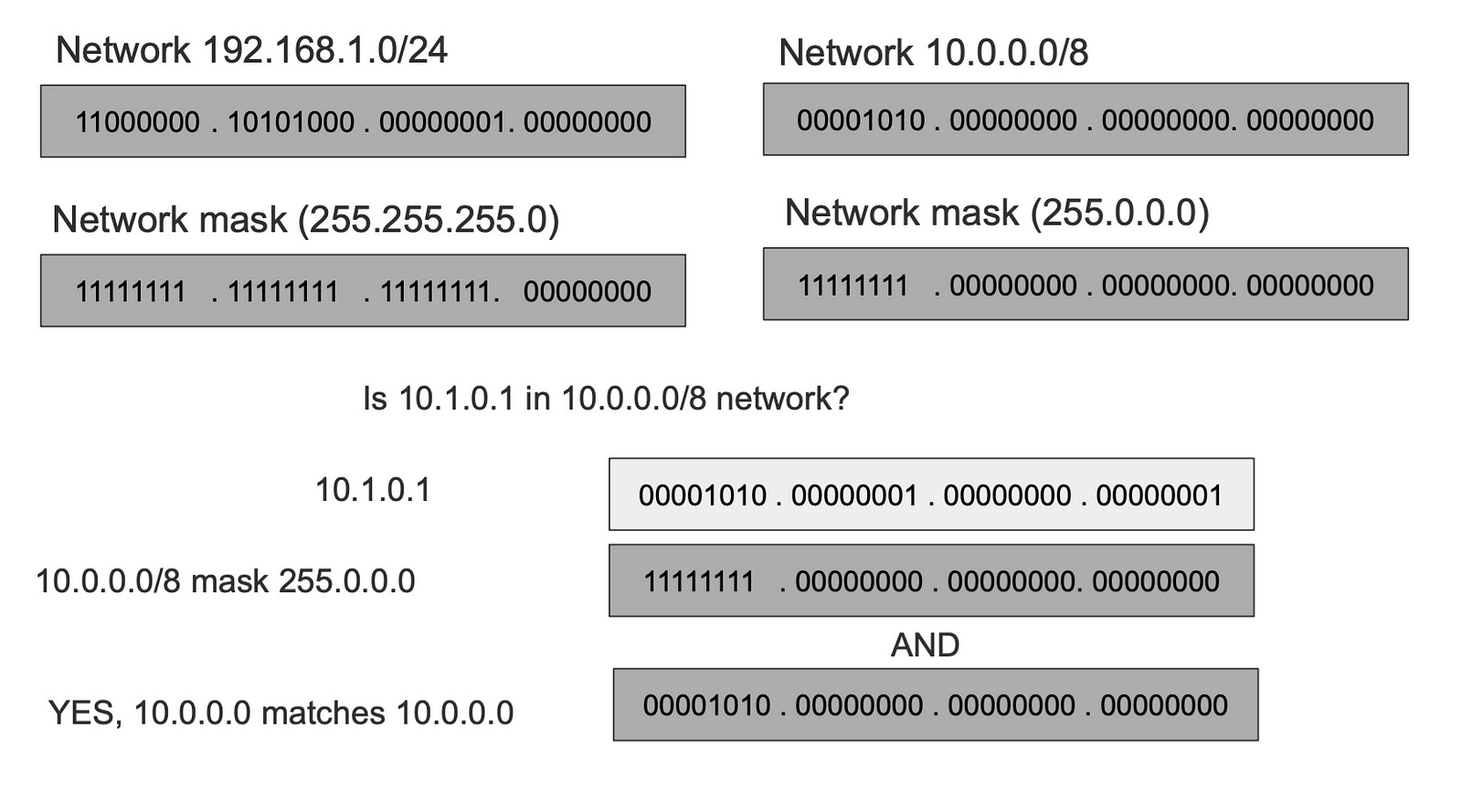
While checking 10.1.0.1 against 10.0.0.0/8 gives us a match.
This is the most important thing to realize about IP networks. The elimination of networks gives us a way to skip tons of devices and ONLY send over the message to the target network.
The rule of IP Networking
The most important thing to understand is that we always use MAC addresses to communicate directly, the IP address just gives us a way to skip a bunch of networks and devices. The rule is as follows:
Given a message to be sent to a target IP Address, we ask a question, is this IP within my network?
1- If the answer is Yes it means I can reach it directly using the MAC Address.
2- If the answer is No it means I cannot reach it directly using the MAC, which means I need to send the message to someone WITHIN my network who knows how to reach that IP address. This device is called the next hop or the gateway.
The next hop asks the same question, the message keeps getting forwarded until bullet one is satisfied.
The above two bullets are the pinnacles of networking across the entire Internet. When we zoom in, all communications are local. Global networking is a series of local networking.
This however raises two questions: Given an IP Address how do I get the MAC address? The second one is how do I know which device in my network knows the way to the target IP address.
The answer to the first question is ARP, and the answer to the second one is the routing table.
ARP — Address Resolution Protocol
Even with IP, you still need the MAC address to send the message. To resolve an IP address to a MAC Address we use a protocol called ARP (Address Resolution Protocol).
ARP clients broadcast a query on the local network asking, “Who has IP X?” Because it is a broadcast frame, all devices within the network get the ARP query, however only the device with an IP Address matching the IP In the frame replies with its MAC.
Emphasis on local network here, ARP packets are not forwarded beyond the local network, because back to rule in bullet 1, only devices within the same network can directly talk to each other via link addresses.

Once we get the MAC address we can send messages directly as we explained in previous sections.
Like any mapping system, ARP has caching in place to prevent asking this question every time. ARP table caches the mapping entries for an IP to a MAC address. You can view your ARP table with this command.
> IP neigh show
192.168.7.185 dev wlp60s0 lladdr xx:xx:xx:90:4c:xx STALE
192.168.7.185 dev enp59s0 lladdr xx:xx:xx:90:4c:xx REACHABLE
192.168.4.1 dev enp59s0 lladdr xx:xx:xx:xx:fd:54 STALE
172.18.0.2 dev br-0a76a61f1824 lladdr xx:xx:xx:xx:00:02 REACHABLE
192.168.7.171 dev enp59s0 lladdr xx:xx:xx:c6:13:aa STALE
192.168.4.1 dev wlp60s0 lladdr xx:xx:xx:xx:fd:54 STALE
192.168.7.171 dev wlp60s0 lladdr xx:xx:xx:xx:13:aa STALE
192.168.7.179 dev enp59s0  INCOMPLETE
fe80::262d:6cff:fe69:fd54 dev wlp60s0 lladdr xx:xx:xx:xx:fd:54 router STALE
fe80::262d:6cff:fe69:fd54 dev enp59s0 lladdr xx:xx:xx:xx:fd:54 router STALE
fe80::c6:8ebe:a668:8d67 dev wlp60s0 lladdr xx:xx:xx:xx:f3:9c router STALE
fe80::c6:8ebe:a668:8d67 dev enp59s0 lladdr xx:xx:xx:xx:f3:9c router STALE
The IP Packet
About time to introduce what the network layer packet looks like. We know the layer 2 frame and the most important fields are destination and source MAC Address. Naturally, the IP Packet’s important fields are the destination IP and the source IP.

The message the client wants to send goes into the IP Packet. The layer 3 IP packet becomes in itself a message that goes inside the layer 2 data link frame.
There are higher level protocols such as TCP headers which have more headers like ports and can carry even higher protocols like HTTP. Those protocols fit into the IP packet as data. This makes networking like the matryoshka doll. In the coming sections I’ll use Yellow as layer 2 frame and Green are layer 3 packet.
Routing and The Router
We know that communications between IP devices in the same network are achieved directly using the link layer and MAC address. However, to communicate with devices in different networks we use Routing.
Routing simply stated is figuring out what device in my network I can “forward” the packet to and it would know how to reach the target IP’s network. That device is often called the gateway, the router, or the next hop.
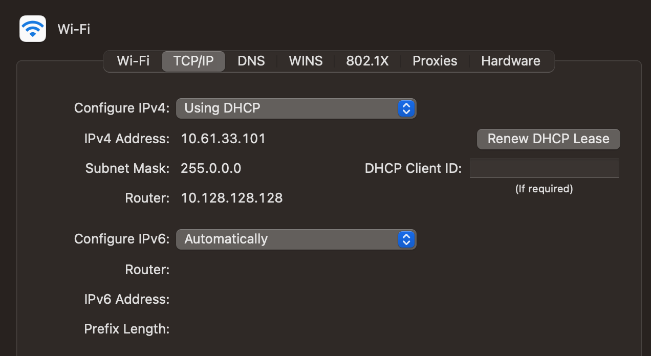
IP addresses can be assigned statically to devices or dynamically using a protocol called DHCP (Dynamic Host Control Protocol). Regardless of how, each device needs a unique IP address on its network, and also needs a Default Gateway where packets to outside networks can be forwarded to.
Without the gateway, the device cannot communicate with outside networks otherwise, that includes the Internet.
The router often belongs to two or more networks, which is why it can route packets to different networks.
Two Networks Configuration
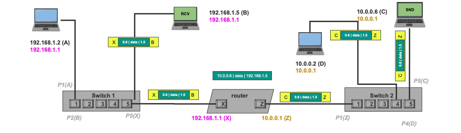
Now that we know the fundamentals, it is time to send to take an example sending IP packets between devices in different networks. Let us discuss configurations first, in this example, we have two networks, 10.0.0.0/8 and 192.168.1.0/24 with the following devices.
One router with two NICs, one acting as a gateway with IP address 10.0.0.1, MAC address for that NIC is Z. The other NIC of the router the router has an IP Address 192.168.1.1 and MAC address (X).
Device 192.168.1.2 with MAC address (A), gateway 192.168.1.1
Device 192.168.1.5 with MAC address (B), gateway 192.168.1.1
Device 10.0.0.6 with MAC address (C), gateway 10.0.0.1
Device 10.0.0.2 with MAC address (D), gateway 10.0.0.1
Switch 1 connecting A to port 1, B to port 2, and router X NIC to port 5.
Switch 2 connecting C to port 6, D to port 4, and router Z NIC to port 1
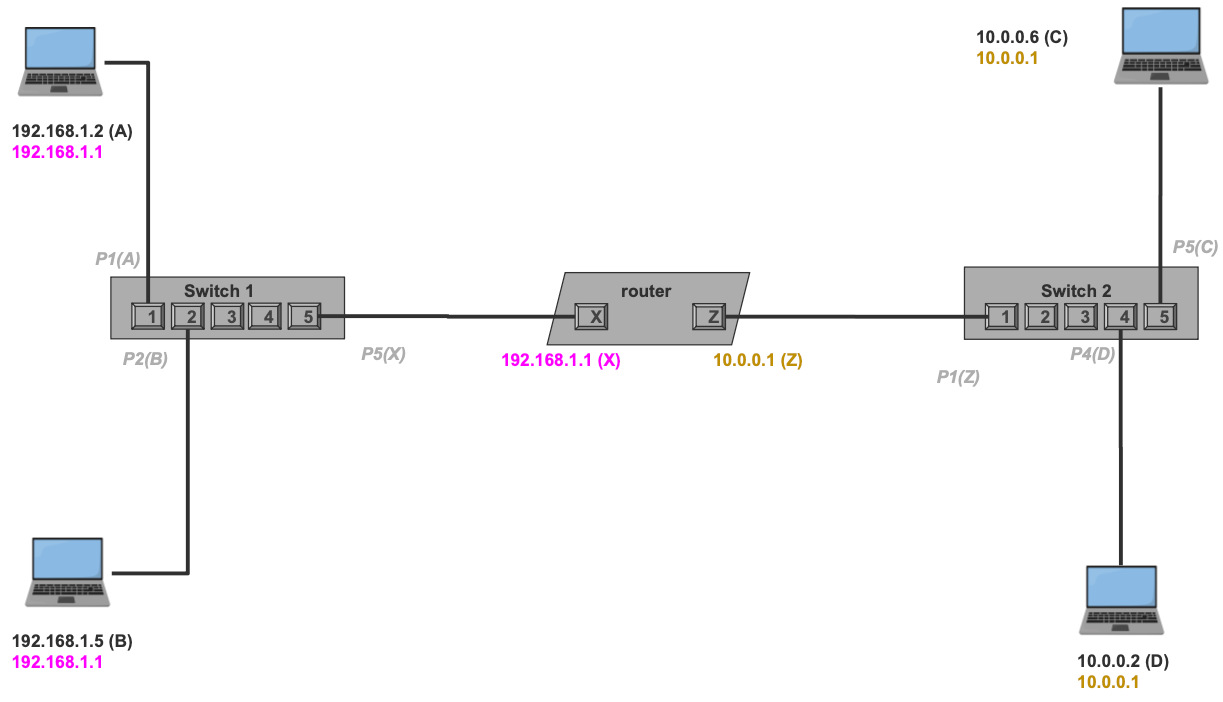
When the devices are connected, the switches will receive the advertisement packets which will link each port to what MAC address on the other side. This will be helpful for future communication where frames will only be forwarded to the right ports and thus right machines. This is notated in the diagram as gray labels.
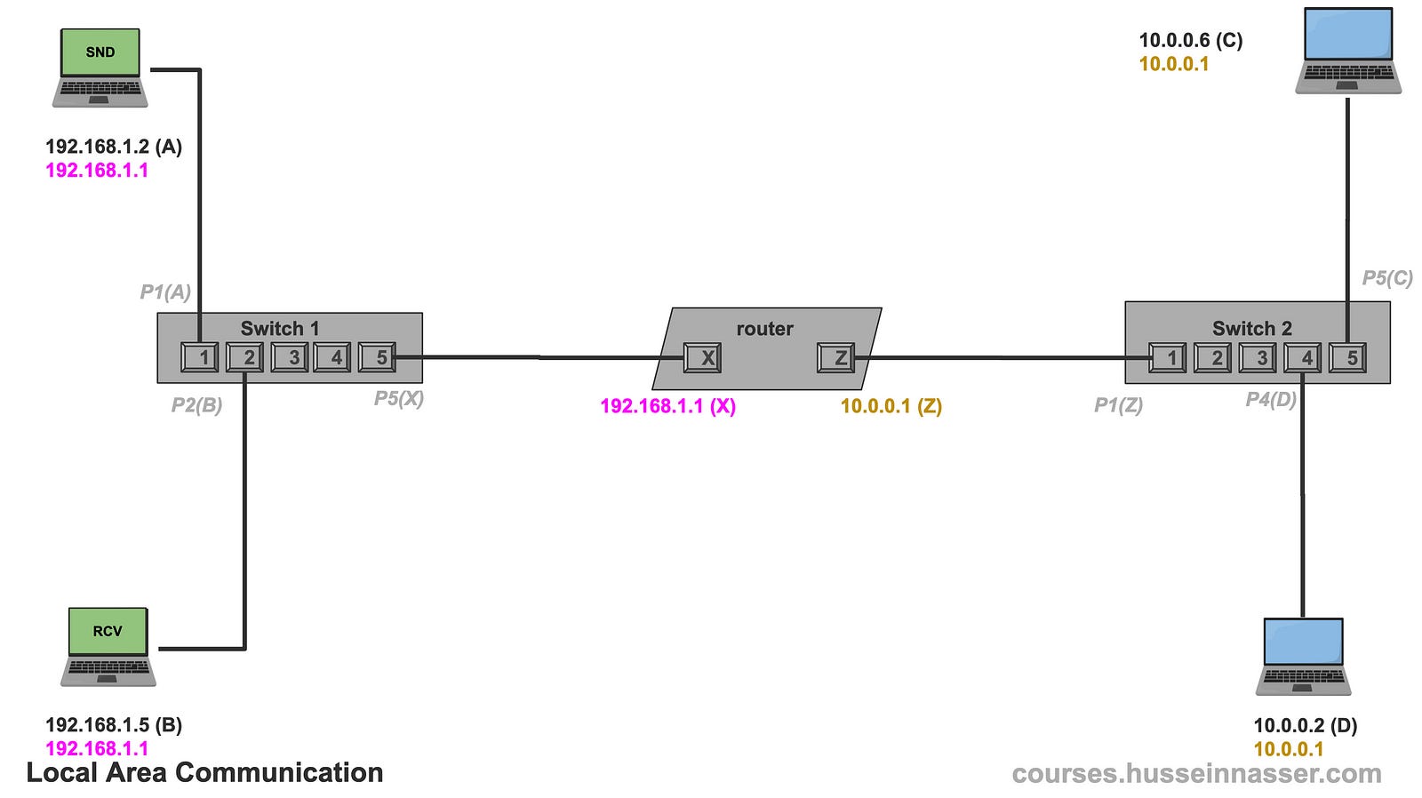
Example — Local Network communication
First, let us take the case where we want to exchange IP packets between two devices in the same network.
Let us say 192.168.1.2 wants to send an IP packet to 192.168.1.5. The packet here could be a TCP SYN or an HTTP GET request, doesn’t matter, what matters is we need to deliver whatever content the app sends from 192.168.1.2 to 192.168.1.5.
For short I’ll use 1.2 to represent 192.168.1.2 and 1.5 to represent 192.168.1.5, didn’t want to make the font small.
The first thing 192.168.1.2 does is check if 192.168.1.5 is within its network, remember bullet 1 from the previous section, it then applies the network mask and sure enough, it is the same network. This means we can do an ARP, get the MAC Address, and send it directly (assuming we don’t have it cached).
192.168.1.2 && 255.255.255.0 = 192.168.1.0
192.168.1.5 && 255.255.255.0 = 192.168.1.0
#Same network! We ARP and get the MAC.
Next 192.168.1.2 sends an ARP query broadcast asking who has the 192.168.1.5. Note that this will only go to machines within the same network, the router will not forward the ARP request to other networks.
Once B receives the ARP request, it replies to A with an ARP reply. A then updates its ARP table with the knowledge that 192.168.1.5 is B.

Now that A has the MAC address of 192.168.1.5 it can put the IP packet in a frame and mark it for B. We know the frame will make it through since it is a local communication. This becomes just another frame from A to B making it through the network.
The fact that the frame has an IP packet is not relevant as far as the network is concerned. And this is the most important thing to understand in networking. That frame can contain an IP Packet which can contain a TCP segment or UDP datagram, which can contain an SSH request, a TLS, HTTP, gRPC, or any other protocol. It just becomes “data” being carried.

Replying to that packet depends on the higher-level protocols, IP Packets do not need responses as TCP segments do. Regardless, B can reply to A if it wishes since the packet has the source IP address and B can use it to ARP 192.168.1.2 to find A.
Example — Inter-Network Communication
Now we add spice. Let us say 192.168.1.5 (B) wants to send a packet to 10.0.0.6 (C ) which is clearly on another network, but B doesn’t know that of course. It needs to apply its subnet mask.
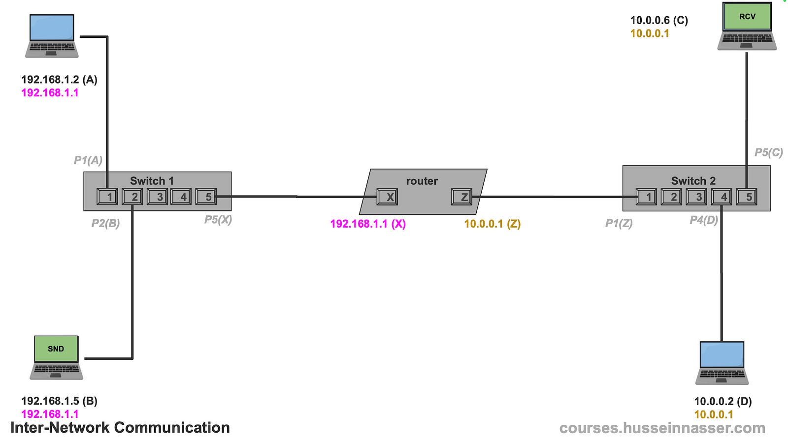
The first thing 192.168.1.5 does is check if 10.0.0.6 is within its network, so it applies its subnet mask and finds out that it is not in its network. So no direct communication is possible. We are at bullet 2 of our rule. Those are the rules.
192.168.1.5 && 255.255.255.0 = 192.168.1.0
10.0.0.6    && 255.255.255.0 = 10.0.0.0
#Not the same network
For that, 192.168.1.5 needs to talk to a machine that is indeed in its network that may know how to reach 10.0.0.6 and that is the default gateway. B’s default gateway is 192.168.1.1 which was configured when the IP stack was set up on that machine.
The next step is we need 192.168.1.1’s MAC address, yes it is just another machine in the network same process applies. Let us do an ARP to discover the router’s MAC address which is X.
Now that we know the gateway’s MAC address, B crafts the packet the destination IP remains 10.0.0.6 but the destination MAC address on the frame becomes X which is the gateway. Clever design.
The router gets the frame, cracks it open to find the packet, and discovers that the destination is 10.0.0.6 which of course is not the same as its own IP 192.168.1.1.
In normal situations, the machine simply drops the packet, since the destination IP address received is not the same as the IP address of the interface. However, the operating system has an option that enables forwarding IP packets, and that is how every router on Earth works. A router is simply a machine with that option turned on. Here is the option in Linux.
net.ipv4.ip_forward=1With that option turned on, the router looks at its other interfaces and it finds that there is one 10.0.0.1 so it checks against it. The same logic applies, this time the router does the work, is 10.0.0.6 in the same network as 10.0.0.1. Notice that we used the network’s subnet mask, we always the interface’s subnet mask.
And indeed they are on the same network, so we can ARP and do our thing.
10.0.0.1 && 255.0.0.0 = 10.0.0.0
10.0.0.6 && 255.0.0.0 = 10.0.0.0
#same network, we can ARP and send
To simplify my diagram a little bit I’m going to assume that the router knows 10.0.0.6 MAC which is C, but you can go through that exercise of doing the ARP.
The router then creates a new frame, with the destination MAC as itself (this time it uses Z because that is the MAC’s interface for 10.0.0.1), and ships the packet as is which makes it to device C.

What if 10.0.0.6 wants to reply? You can walk through that example, it has 192.168.1.5 as the source IP address but it's not in its network so it sends it to the gateway which then does the same and forwards it to the other network.

Multiple network configurations where it breaks
Now let us introduce a hurdle where the concept of the default gateway breaks down. Because I don’t like magic, I will show you that a router is just a machine. I will make 10.0.0.6 from our network which already has a default gateway into a router by adding a network interface to it and connecting it to another machine. The new network is 172.16.6.0/24.
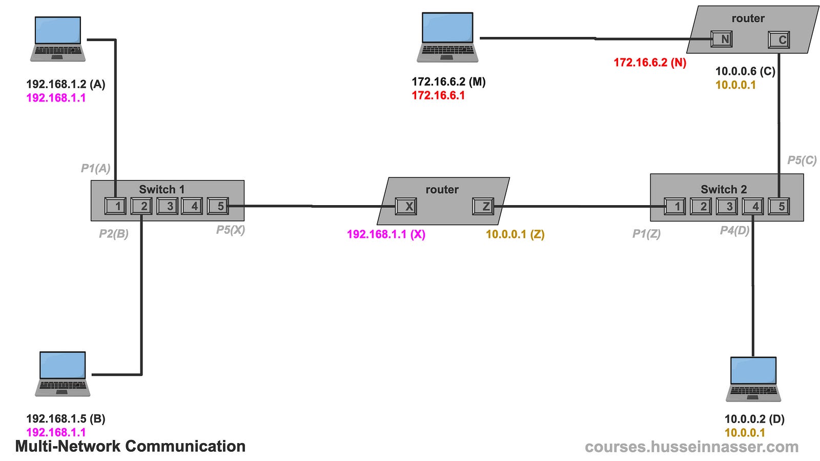
Now let us say 10.0.0.2 wants to send a packet to 172.16.6.2, it will start applying the same logic and find out that 172.16.6.2 is not in its network.
10.0.0.2   && 255.0.0.0 = 10.0.0.0
172.16.6.2 && 255.0.0.0 = 172.0.0.0
So it sends the packet to its default gateway, but even the gateway has no clue how to reach that network because the only other interface it knows is 192.168.1.1 which doesn’t match.
From now on I’ll assume ARP has been performed and cached, just so I don’t have to draw the diagrams every time.
In our example, the router didn’t have a default gateway so it dropped the packet, but if it did it would have forwarded the packet to its gateway and it would probably also get nowhere. The packet is lost forever either way.
So how do we solve this? Meet the routing table.
Meet the Routing Table
As we demonstrated before in the previous section, the concept of the Default Gateway by itself is useful to forward packets to a single device that may know where that IP needs to go. However, it breaks quickly when we have more networks and multiple paths, we need more granularity to control what specific next hop or gateway for different networks.
The truth is the knowledge of which next hop leads to what network is stored in a routing table. There is always a routing table, I just delayed introducing it to make you appreciate the reason behind it.
I believe in the question of why in everything in software engineering. “Why” is an uncomfortable question, because often when asked you will discover that most of things we do don’t have a deep rooted reason. A brave engineer asks “Why” and have no hesitating of dropping the technology if it doesn’t he couldn’t find a reason.
Here is an example of a routing table of the machine 10.0.0.2 in network 10.0.0.0/24
To go to 10.0.0.0/8 use link
To go to ANY use 10.0.0.1
Remember the two bullets for the rules of IP networking? Those two can also be simplified by the routing table as well. We no longer need to check if an IP is in the same network. We can simply look at the table and it will tell us if we can or cannot communicate directly via link.
The first route To go to 10.0.0.0/8 use link tells the machine that it can reach any devices on 10.0.0.0/8 via the link directly, ie it is safe to ARP and communicate via data link. Removing this route will prevent the machine from communicating with any device in its network.
The second rule To go to ANY use 10.0.0.1 is essentially the default gateway, if you don’t know where to send it, just use 10.0.0.1 as a gateway or the next hop. Note that even addresses on the Internet will use this route.
Now tell me, how would you solve our problem from earlier? The problem is 10.0.0.2 used the default gateway which is the second route. What we need is a route that says to use a different router that we know it knows and that the router is indeed also in our network. It is 10.0.0.6. Note that 10.0.0.6 is in the same subnet as 10.0.0.2, otherwise this won’t work.
Remember the next hop MUST be in the same subnet as the machine because there is no communication if there is no direct link.
To go to 10.0.0.0/8 use link
To go to ANY use 10.0.0.1
To go to 172.16.6.0/24 use 10.0.0.6
The new route tells the machine to send the packet to 10.0.0.6 if the target IP is in 172.16.6.0/24. This means the 10.0.0.6 has two interfaces (NICs), one in 10.0.0.0/8 and one in 172.16.6.0/24
This is the power of the routing.
Routing tables differ from one OS to another but these are the most important fields.
- Destination network
- Subnet mask
- Gateway (next hop)
- Interface (which NIC to use)
- Metric (preference level)
When no match is found, the default route is used.
Using the Routing Table for fine-tuning
With the new rule, 10.0.0.2 looks up 172.16.6.2 in the routing table, it finds that there is a rule that applies.
To go to 172.16.6.0/24 use 10.0.0.6It then ARPs the 10.0.0.6 to get its MAC, discovers its C, crafts an IP packet with destination 172.16.6.2, and places it in a frame destined to C. C or 10.0.0.6 receives it and knowing it has IP forwarding enabled, it looks up the IP and finds that it matches its other interface 172.16.6.1 and forwards the packet. The router creates a new frame with a destination MAC (M) after doing an ARP to get the MAC of 172.16.6.2 and places its own MAC address (N) as the source.
Note, if 172.16.6.2 wants to reply to 10.0.0.2 it will use its default gateway 172.16.6.1 and luckily we are saved because that gateway does have 10.0.0.0/8 at its other interface. If this was not the case we would need to add a new route.
How about the Internet?
The fundamentals of the Internet work very similarly to what we just discussed. ISPs, or Internet Service Providers, often own a group of networks. Those groups of networks are called Autonomous Systems, or AS for short.
Each AS has a unique number and owns a list of networks. Big companies own their own AS as well. Here is an example of Facebook AS with a few of its networks.
AS32934 FACEBOOK, US
173.252.88.0/21
57.144.198.0/23
57.144.142.0/23
157.240.227.0/24
I like to use this website to look up the IP networks for any AS, https://hackertarget.com/as-ip-lookup / Try it, put your own ISP, no matter how small it is, it is there.
So then we have a collection of autonomous systems which the routing tables have no clue what that is, but it does know how to deal with networks.
The game becomes for the AS to “advertise” the list of networks to its neighbor router. To reach any of these networks, use me as your next hop, I.e. I’m your gateway for any of these networks. The router updates its routing table with the knowledge. That router tells its neighbor router but changes the next hop to itself. Because you have to remember that the next hop must be in the same network.
What we just described is the job of the BGP, the Border gateway protocol which is probably another post. However, the job of the BPG is to simply update the routing table.
The routing table is the pinnacle of all decisions and the source of truth. Other protocols simply update the routing table.
On your laptop, if you visit Google.com (142.250.72.23), the machine will consult its local routing table and discover that 142.250.72.23 is outside its network ( 192.168.1.0/24), so it forwards the packet to the home router 192.168.1.1 which has WAN access (Wide area network). Your home router has two interfaces, one with 192.168.1.1 and the other with the ISP with a unique public IP address (sometimes private depending on the ISP setup).
The router then consults its local routing table and forwards the packet to its gateway on one of the ISP's routers. That ISP router will have a richer routing table updated by BGP which details exactly what next hop will get us to 142.250.72.23, it will be something like this.
To go to 142.250.72.0/24 use X The packet will be forwarded until it arrives at the destination.
Note BGP routers have 900K+ routes as we are getting more and more networks, especially with IPv6 as well. This is another topic, searching this thing is a database problem.
Useful Commands
Here are some useful commands, specifically but Linux Ubuntu.
#print ARP table
>ip neigh

192.168.1.1 dev eth0 lladdr 00:11:22:33:44:55 REACHABLE

#print routing table
>ip route show

default via 192.168.1.1 dev eth0
192.168.1.0/24 dev eth0 proto kernel scope link src 192.168.1.100

#list all NICs
>ip link show
1: lo: <LOOPBACK,UP,LOWER_UP> mtu 65536 qdisc noqueue state UNKNOWN mode DEFAULT group default
2: eth0: <BROADCAST,MULTICAST,UP,LOWER_UP> mtu 1500 qdisc mq state UP mode DEFAULT group default
3: wlan0: <BROADCAST,MULTICAST> mtu 1500 qdisc noop state DOWN mode DEFAULT group default

#ifconfig
>ifconfig

eth0: flags=4163<UP,BROADCAST,RUNNING,MULTICAST>  mtu 1500
        inet 192.168.1.100  netmask 255.255.255.0  broadcast 192.168.1.255
        inet6 fe80::a00:ffff:ffff:66a1  prefixlen 64  scopeid 0x20<link>
        ether 08:00:aa:aa:aa:aa  txqueuelen 1000  (Ethernet)
        RX packets 14575  bytes 20122345 (20.1 MB)
        RX errors 0  dropped 0  overruns 0  frame 0
        TX packets 10328  bytes 9876543 (9.8 MB)
        TX errors 0  dropped 0 overruns 0  carrier 0  collisions 0

lo: flags=73<UP,LOOPBACK,RUNNING>  mtu 65536
        inet 127.0.0.1  netmask 255.0.0.0
        inet6 ::1  prefixlen 128  scopeid 0x10<host>
        loop  txqueuelen 1000  (Local Loopback)
        RX packets 540  bytes 43200 (43.2 KB)
        RX errors 0  dropped 0  overruns 0  frame 0
        TX packets 540  bytes 43200 (43.2 KB)
        TX errors 0  dropped 0 overruns 0  carrier 0  collisions 0
Practical Example
Perhaps the best tool to test your newfound networking skills on is Docker. With Docker, you can create virtual networks and host containers with services and connect to them.
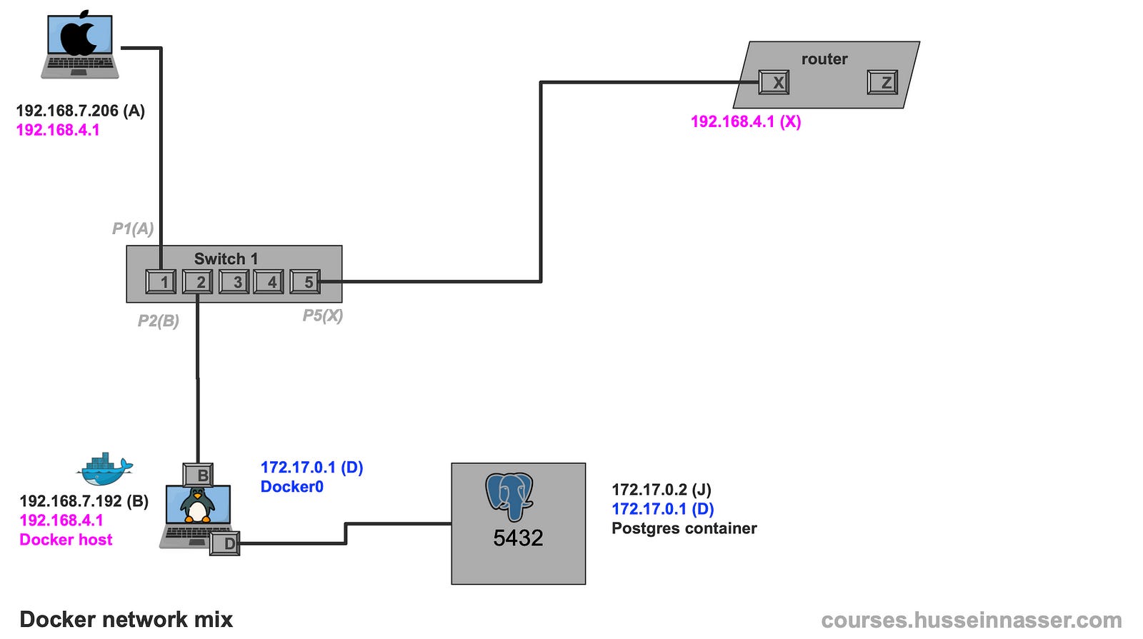
In this example, I have LAN network 192.168.1.0/22. My Macbook IP is 192.168.7.206, I have a Linux machine running a Docker host on 192.168.7.192. The gateway is 192.168.4.1.
On 192.168.7.192 by default, we get a virtual docker network NIC docker0 with 172.17.0.1/16 network when we install docker by default. I will spin up a new Postgres instance which will get assigned an IP address on the docker0 network.
docker run --name pg17 -e POSTGRES_PASSWORD=postgres -p 5432:5432 -d postgres:17By doing docker inspect pg17 we can discover the IP address assigned to my postgres instance, it is 172.17.0.2
 docker inspect pg17 | grep IPAddress
 "IPAddress": "172.17.0.2",
                    "IPAddress": "172.17.0.2",
This is my current configuration.
From A 192.168.7.206 we can easily access the B 192.168.7.192, telnet on the SSH port works. This is because of the lessons we learned previously.
Macbook (A@192.168.7.206)> telnet 192.168.7.192 22
Trying 192.168.7.192...
Connected to alien.
Escape character is '^]'.
SSH-2.0-OpenSSH_8.9p1 Ubuntu-3ubuntu0.13
From the same machine I cannot access the Postgres container 172.17.0.2 on port 5432, that is because there is no route to 172.17.0.0/16
Macbook (A@192.168.7.206)> telnet 172.17.0.2 5432
Trying 172.17.0.2...
If we try this from the Linux machine I can indeed access the Postgres container because there is a direct path to it through the docker0 interface on the same machine. Also referred to as a bridge. Note that the source IP will be the docker0 network 172.17.0.1 in this case.
The OS selects the best source IP based on the applicable network if the packet is initiated from the same machine, this is only if the packet originated from the same machine. Forwarding preserves the source ip, unless NAT is setup. Let us talk about this in another post.
Linux (A@192.168.7.192)> telnet 172.17.0.2 5432
Trying 172.17.0.2...
Connected to 172.17.0.2.
Escape character is '^]'.
To solve this we add a new route on the Macbook A to use 192.168.7.206 as a gateway for the docker network 172.17.0.0/16
Macbook (A@192.168.7.206)> sudo route -n add -net 172.17.0.0/16 192.168.7.192
add net 172.17.0.0: gateway 192.168.7.192
Now if we try again, we can get full access to the Postgres container!
Macbook (A@192.168.7.206)> telnet 172.17.0.2 5432
Trying 172.17.0.2...
Connected to 172.17.0.2.
Escape character is '^]'.
This is the final configuration
Protocols That Update Routing Tables
As we so in the previous section, routing tables aren’t static. User-space protocols like DHCP, OSPF, and BGP dynamically update them:
- DHCP assigns IPs and default gateways.
- OSPF maps out the shortest paths between networks.
- BGP manages inter-network routing across the Internet.
At the end a simple route with a metric is written, how it got there is irrelevant. Machines just follow their routing tables.
Just imagine if we had to deal with MAC addresses instead of IP networks.
Summary
Routing is not magic — it’s a well-orchestrated system of tables, addresses, and rules. Starting from simple MAC-based communication, we’ve scaled to a global web of interconnected routers using IP addresses and routing protocols. Once you understand that all these systems just update and use the routing table, the whole network architecture begins to make sense.
Stay curious and explore further — each layer you understand opens up new levels of network mastery.
If you enjoyed this article, check out my premium courses. I talk in detail about networking, backend engineering, databases, and operating systems.
Excellent writeup.